

RDI DVL Configuration
Objective: To configure the RDI Workhorse DVL to support the use of an external Attitude Heading Reference System (AHRS).
Figure 1. RDI Workhorse heading Alignment
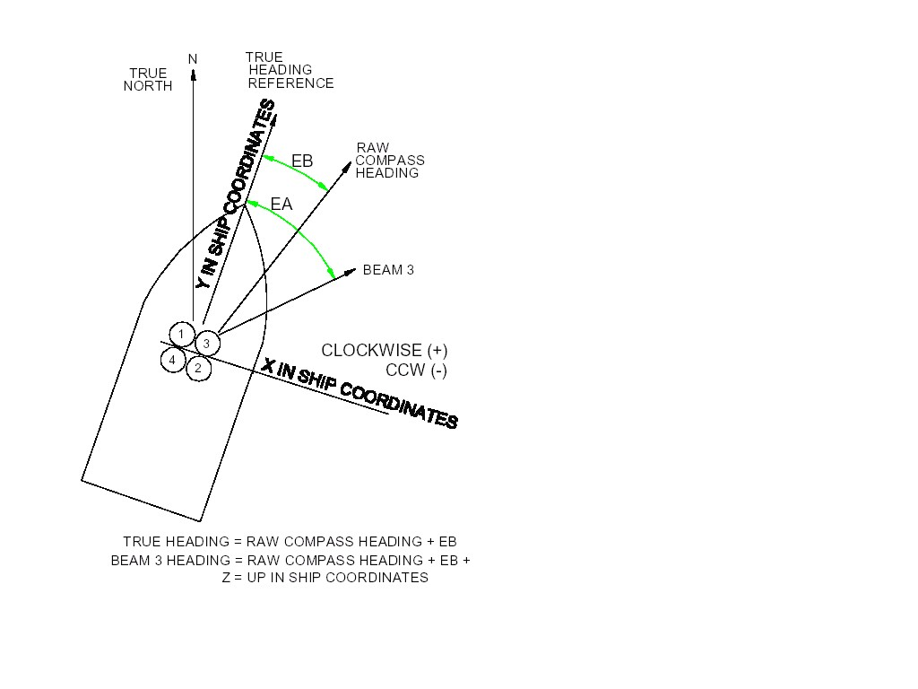
Table 1. Required DVL Configuration:
|
Item
|
Name
|
Description
|
Default
|
Setting
|
| |||
|
1
|
CR-Settings
|
Resets the DVL command set to factory/user settings. CR keeps the present baud rate and does not change it to ROM setting
|
CR0
|
CR1
| ||||
|
2
|
EA-Heading Alignment
|
To reference beam 3 to vehicle centerline or Y-Axis, in 100th of degrees. Clockwise(+) see fig 1
|
EA00000
|
EA+04500
| ||||
|
3
|
EB-Heading Bias
|
To convert compass heading to true magnetic reference (NOT USED) for JSL [100th of degrees]
|
EB00000
|
EB00000
| ||||
|
4
|
EC-Speed of sound
|
Sets the DVL speed of sound value that is used to scale the velocity values by [m/s]. Note the actual speed of sound is determined by the onboard CTD and all velocities are scaled by the ratio of the CTD speed of sound to 1500 m/s
|
EC1500
|
EC1500
| ||||
|
5
|
EH-Heading
|
Sets the DVL heading angle [100th of degrees]. Note EZ heading field = 0, the DVL uses the EH value instead of the DVL internal heading sensor.
|
EH00000
|
EH00000
| ||||
|
6
|
EP-Pitch
|
Sets the DVL pitch angle [deg]. Note EZ Pitch field = 0, The DVL uses the EP value instead of the DVL internal pitch sensor.
|
EP0000
|
EP0000
| ||||
|
7
|
ER-Roll
|
Sets the DVL Roll angle [deg]. Note EZ Roll field = 0, The DVL uses the ER value instead of the DVL internal roll sensor.
|
ER0000
|
ER0000
| ||||
|
8
|
ES-Salinity
|
Sets the water’s salinity value [PSU]
|
ES35
|
ES35
| ||||
|
9
|
ET-Temperature
|
Sets the water’s temperature [100th of deg C]. Note EZ temp field = 0, The DVL uses the ET value. This must be a constant otherwise the DVL will adjust the speed of sound and velocity values based upon a value of other then 1500 m/s. See EC above
|
ET2500
|
ET2500
| ||||
|
10
|
EX-Coordinate Transformation
|
Sets the coordinate transformation processing flags. For JSL set so DVL provides the velocity components X,Y,Z wrt ship coordinates (see Fig 1). The EA command value is used, internal heading is not used and Roll/pitch will not be used since bit 3 of EZ =0.
Bit fields:
EX10…= Ship coord,
EX..0.. = do not use DVL Roll/Pitch,
EX…11 allow 3-beam solution and bin mapping
|
EX11111
|
EX10011
| ||||
|
11
|
EZ-Sensor Source
|
Selects the source of the environmental sensor data. Format Ezcdhprst
c- Speed of sound = 0 = manual EC 1500
d – Depth = 1 = DVL depth sensor
h – heading = 0 = manual EH 0.00
p – pitch = 0 Manual EP 0.0
r – roll = 0 = Manual ER 0.0
s – Salinity = 0 = Manual ES 35 ppt
t – temp = 1, (Manual ET 25.0 C)
|
EZ1111111
|
EZ0100001
Note: Depth and Temp required for Sound Velocity
| ||||
|
12
|
CF-Flow ctrl
|
Flow Ctrl (EnsCyc;PngCyc;Binry;Ser;Rec)
Auto ensemble, auto ping, bin, serial, no recording
|
|
CF11110
| ||||
|
13
|
CB-Baud rate
|
DVL Serial port settings, defaults to 9600,8,1,n (CB411)
Set to 19200,8,1,n (CB511)
|
CB411
|
CB511
| ||||
|
14
|
PD-Data select
|
Selects the type of ensemble output data structure. Set to PD6 “Send a special DVL ASCII data stream”
|
PD0
|
PD6
| ||||
|
15
|
TE-Time Per Ensemble
|
Sets the minimum interval between data collection cycles, default TE01:00:00.00
|
TE01:00:00.00
|
TE00:00:00.00
| ||||
|
16
|
TF-First ping
|
TF- Time to First Ping. Sets the time to wake up DVL and start data collection
|
**/**/**,**:**:**
|
**/**/**,**:**:**
| ||||
|
17
|
TP-Time Between Pings
|
Time Between Pings. Set the minimum time between pings.. Format TPmm:ss.ff (mm-Min, ss-sec, ff-hsec)
|
TP01:20.00
|
TP00:00.00
| ||||
|
18
|
BP-Bottom Pings
|
Bottom Track pings per ensemble. Sets the number of bottom pings to average together in each data ensemble
|
BP001
|
BP001
| ||||
|
19
|
CK
|
Save settings (Verify settings)
|
|
| ||||
|
20
|
CS
|
Start pinging
|
|
| ||||
Configuration settings
>B?
BA = 030 ----------------- Evaluation Amplitude Min (1-255)
BB = f934 ---------------- High Bandwidth Maximum Depth (dm)
BC = 220 ----------------- Correlation Magnitude Min (0-255)
BD = 000 ----------------- Delay Re-Acquire (# Ensembles)
BE = 1000 ---------------- Max Error Velocity (mm/s)
BF = 00000 --------------- Depth Guess (0=Auto, 1-65535 = dm)
BG = 0,30,000 ------------ Restricted Xmit: Enable; MaxXmit[%]; MaxXmit[ms]
BH = 3,0,0000 ------------ BM6 Configuration BW; Code; Velocity(cm/s)
BI = 020 ----------------- Gain Switch Depth (0-999 meters)
BK = 0 ------------------- Layer Mode (0-Off, 1-On, 2-Lost, 3-No BT)
BL = 160,0320,0480 ------- Layer: Min Size (dm), Near (dm), Far (dm)
BM = 5 ------------------- Mode (4 = Def, 5 = Coherent, 6 = No Amb. Res.)
BN = 0,999 --------------- Speed Log Hold/Drop Control (hold=1,timeout)
BO = 025 ----------------- Distance Measure Filter Constant (1/100ths)
BP = 001 ----------------- Pings per Ensemble
BR = 0 ------------------- Resolution (0 = 4%, 1 = 2%, 2 = 1%)
BS ----------------------- Clear Distance Traveled
BW = 00001 --------------- Water Reference Interval (0-65535 pings)
BX = 02500 --------------- Maximum Depth (10-65535 dm)
BZ = 004 ----------------- Coherent Ambiguity Velocity (cm/s radial)
>C?
CA = 000 ----------------- Periodic Output 1/10 sec. (0-Off, [10-600])
CB = 511 ----------------- Serial Port Control (Baud [5=19200]; Par; Stop)
CF = 11110 --------------- Flow Ctrl (EnsCyc;PngCyc;Binry;Ser;Rec)
CK ----------------------- Keep Parameters as USER Defaults
CL = 1 ------------------- No Sleep Between Pings (0 = ON, 1 = OFF)
CN = 1 ------------------- Save NVRAM to recorder (0 = ON, 1 = OFF)
CR # --------------------- Retrieve Parameters (0 = USER, 1 = FACTORY)
CS ----------------------- Go (Start Pinging)
CT = 1 ------------------- Turnkey (0 = OFF, 1 = ON)
CX = 0 ------------------- Trigger Enable (0 = OFF, 1 = ON)
CY = 8800C000 ------------ Clear Error Status Word
CZ ----------------------- Power Down Instrument
>CK
[Parameters saved as USER defaults]
>E?
EA = +04500 -------------- Heading Alignment (1/100 deg)
EB = +00000 -------------- Heading Bias (1/100 deg)
EC = 1500 ---------------- Speed Of Sound (m/s)
ED = 00000 --------------- Transducer Depth (0 - 65535 dm)
EF = 100 ----------------- Pressure Smoothing Constant (1-100,100=off)
EH = 00000 --------------- Heading (1/100 deg)
EP = +0000 --------------- Tilt 1 Sensor (1/100 deg)
ER = +0000 --------------- Tilt 2 Sensor (1/100 deg)
ES = 35 ------------------ Salinity (0-40 pp thousand)
ET = +2500 --------------- Temperature (1/100 deg Celsius)
EX = 10011 --------------- Coord Transform (Xform:Type; Tilts; 3Bm; Map)
EZ = 0000000 ------------- Sensor Source (C;D;H;P;R;S;T)