

Three Axis Magnetometer Calibration
Creating a Magnetometer Calibration
1. Launch the IPS with the USB security key.
2. If you know the location of the magnetometer calibration create an IPS waypoint now for later use, see section 7.2 below.
3. Select File->Export Sensor XYZ from the main menu.
4. If required, and you are using the $PIMAG or SLD data format., you can specify the region of data to be processed. Set the “Time Bounds”, under the Data Bounds tab. See below for examples of the data formats used.
1. Check (enable) the “Use Time Bounds” and [Apply].
5. Under the “Process and Export” tab set the “Sensor File” to mag calibration data file in either the raw Honeywell HMR2300, HMR3000 (XDR) ASCII data formats, the $PIMAG formatted text or SLD *.csv file.
6. Click on the [3-Axis Mag Cal] button.
7. Enter in the total earth field Nanotesla [nT] for the specific Mag calibration site.
1. Use your latitude and longitude or zip code to find the total earth field at the following website http://www.ngdc.noaa.gov/geomag-web/#igrfwmm.
2. Or select an IPS waypoint near the calibration area, you may use the waypoint entered earlier. The IPS will automatically calculate the earth’s magnetic field using the Enhanced Magnetic Model (EMM) based on the waypoint latitude and longitude and the first data point’s UTC date-time at sea level.
3. Or enter the default value of 50,000, however this may cause a small bias relative to Earth's actual magnetic field.
8. The processed magnetometer calibration data should be represented as a single green line that overlaps the blue Earth field line. If this is the case, click on the [Save calibration] button to generate a PDF calibration report including a calibration plot and a Mag calibration text file with the calibration coefficients. If you do not get a desirable result, try one of the following suggestions. If the points are scattered collecting more data may improve the calibration. If the line has a slope, this is usually caused by the temperature not being at a steady state, the magnetometer’s temperature must equilibrate to the temperature that you are calibrating in. This applies only to non-temperature compensated magnetometers.
Magnetometer Output (Machine Readable) Text File Format:
[TotalField]51508
[Threshold]184
[a11]0.915631199985504
[a12]0.00729029969385857
[a13]0.0137476726049316
[a21]0.00729029969385852
[a22]0.930359671865496
[a23]-0.00217196119162317
[a31]0.0137476726049316
[a32]-0.0021719611916232
[a33]0.930237010025602
[b1]0.132084211077783
[b2]0.046174601186279
[b3]0.235802094970093
[StdDev]0.000922
3-Axis Magnetometer Calibration Plot
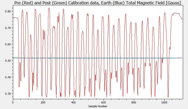
Figure 1. Example of a 3-axis magnetometer calibration plot showing the raw magnetometer data in red and the same magnetometer data processed using the magnetometer calibration coefficients in green. If the calibration is valid the green line should overlap the blue line that is the Earth’s total magnetic field at the calibration site in Gauss [G].
The calibration of the three axis magnetometer requires it to be moved in three dimensions, if possible through a variety of heading, roll and pitch positions in an area that is free of magnetic clutter (away from steel ships, commercial docks etc.)
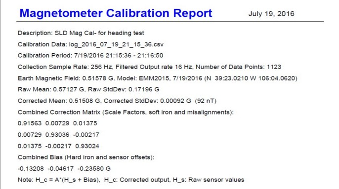
Example Magnetometer PDF report (Cal plot image not show below, see figure 1).
Georeferencing of Magnetometer data (IPS $PIMAG)
1. With either valid real time data being collected or an IPS file loaded into IPS.
1. Click on File->Export Data -> Sensor XYZ.
1. Select the “Process Export” tab.
1. Click on the Sensor File” of IPS Magnetometer file ($PIMAG or SLD).
1. Click on “Support File” to set the corresponding magnetometer calibration file generated by the IPS (*.txt).
1. Set the IPS target number.
1. Click on button Georeferenced Local Sensor Data.
Note: HMR3000 or HMR2300 data files can be converted from raw (uncompensated) to total field compensated using the same procedure as Georeferencing IPS $PIMAG or SLD data files. In this case no valid navigation data needs to be loaded into IPS.
IPS File Formats Supported (using UTC time):
If you are using a format currently not supported, contact EdgeTech and we will add the required format.
$PIMAG,HHMMSS.sss,MM-dd-yyyy,x,y,z<CR><LF> where X,Y,Z are in Gauss. For Example:
$PIMAG,180023.803,05-08-2014,0.209067,-0.189467,-0.373400
Or
Honeywell HMR-2300 ASCII format 28 bytes (fixed field)
SN | X1 | X2 | CM | X3 | X4 | X5 | SP | SP | SN | Y1 | Y2 | CM | Y3 | Y4 | Y5 | SP | SP | SN | Z1 | Z2 | CM | Z3 | Z4 | Z5 | SP | SP |<cr><lf>
Where, SN= negative sign or a space, CM-comma, SP-Space. For example:
4,079 - 1,250 - 5,539
- 47 485 - 6,921
Honeywell HMR-3000 ASCII format
$HCXDR,A,37.8,D,PITCH,A,-45.0,D,ROLL,G,2696,,MAGX,G,8681,,MAGY,G,-3536,,MAGZ,G,9754,,MAGT*1C
Or
wwww.RIEmbedded.com, SLD AHR 9Axis Orientation Logger (inexpensive MEMS device)
Default ASCII format:
SLD-AHR Default format settings (using UTC time):
www.SimpleMEMS.com
Battery Voltage 4.152 Volts
Sample Rate (SR) (256) Hz
Timestamp Format (TSF) (0) Absolute
Accelerometer Status (AS) (1) On
Acceleration Format (AF) (0) G's
Accelerometer Full Scale (AFS) (2) +/- 2 G's
Magnetometer Status (MS) (1) On
Magnetic Field Format (MFF) (0) Gauss
Magnetic Field Gain (MFG) (1300) milli-gauss
Gyroscope Status (GS) (1) On
Angular Rate Format (ARF) (0) DPS: Degrees per second
Angular Rate Full Scale (ARFS) (250000) milli-degrees per second/250 DPS
Example SLD *.csv log file header and data
Year Month Day Hour Minute Second Sub-Second Acceleration-X (G's) Acceleration-Y (G's) Acceleration-Z (G's) MagneticField-X (Gauss) MagneticField-Y (Gauss) MagneticField-Z (Gauss) AngularRate-X (dps) AngularRate-Y (dps) AngularRate-Z (dps)
2016 7 19 21 15 36 0 -0.987 0.067 0.003 -0.6536 -0.2364 -0.3051 2.7 2.4167 -7.8
2016 7 19 21 15 36 0.0039 -0.99 0.064 0.004 -0.6491 -0.2373 -0.3061 2.2 2.8333 -8.275
2016 7 19 21 15 36 0.0078 -0.986 0.064 0 -0.6491 -0.2373 -0.3061 1.6667 3.175 -8.5833
2016 7 19 21 15 36 0.0117 -0.984 0.062 -0.005 -0.65 -0.2373 -0.3071 1.3583 3.1583 -8.7
2016 7 19 21 15 36 0.0156 -0.975 0.057 -0.01 -0.65 -0.2373 -0.3071 1.525 2.975 -8.2917