

Sheltered Water Calibration
IPS Requirements
• Hydrophone X,Y,Z offsets w.r.t CRP/still water line
• Correct sound velocity
• GPS input
• True ship’s heading
• Time sync’ed enabled in IPS
• USBL time sync’ed
• TM filtering set to average 0 points
• Hydrophone heading, roll & pitch mounting angles set to zero in TM
• Beacon deployed at a known depth with TM depth set to manual and “input” or the use of a depth telemetry beacon
• Collection of sufficient number of data samples (typically once every two seconds)
• Data is collected with good geometry, by following the suggested calibration pattern (figure X) at a maximum range of 3-5 time the beacon depth
Sheltered Water Calibration
1. Select site
1.1. On-site Sound Velocity Cast SV _________m/s {for shallow water, SV at hydrophone will be suffice).
1.1.2. If available enter in vessel’s depth sounder ___________m/sec.
1.2. Determine depth of beacon site using calibrated depth sounder.
1.2.1. Actual site Depth ___________m.
2. Ready transponder with surface float and weight for deployment at site of depth. Set the actual line length for 10-20 ft more than the actual depth.
2.1. Set the beacon up to float or be positioned 1.0 meter above the bottom using beacon float collar or stand.
2.2. Beacon Depth ____________m.
3. Power on Beacon
4. Deploy the beacon at site and log actual deployment position (take a fix).
Lat__________________ Long_________________
5. Enter into the Navigation plot the waypoint for the calibration pattern (figure 1).
6. Center on beacon waypoint and zoom in to a grid scale such that the individual squares are about 3-5X the depth of the beacon. For example, if the beacon is deployed at a depth of 50 meters zoom in so an individual squares are about 200 meters. The vertical size of a grid square is enclosed in brackets [ ] in the status bar at the bottom of IPS, as shown below:
7. Have the vessel slowly (2-3 knots) follow the calibration pattern (figure1) and collect two sets of data (into one file).
8. Run the USBL calibration routine (See procedure below).
9. Calibration Hydrophone Mounting angle Offsets:
9.1. Heading _______________ deg (+ CW – alignment mark rotated ”to Stbd” )
9.2. Roll___________________ deg (+ Port side Up – Top of Hyd port side is Up)
9.3. Pitch__________________ deg (+Bow up – Hyd Fwd Top edge Up)
10. Enter Calibration Hydrophone Mounting angle Offsets into IPS as reported.
11. At main corners of calibration pattern verify tracking quality.
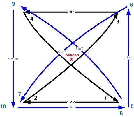
Figure 1. Suggested USBL calibration pattern. If possible, the vessel should not operate at a horizontal range greater than 5 times the depth of the beacon.